Zeitschrittsimulation: Ungesteuerter 6-Puls-Gleichrichter
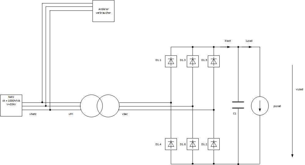
Simuliert wird ein ungesteuerter 6-Puls-Gleichrichter mit Trafo, Quellimpedanz aus uk und DC-Zwischenkreiskondensator. Die Last ist als konstante Leistung modelliert.
Ergebnisse ueber eine Netzperiode
DC Werte
vDcLink,avg-
iLoad,avg-
pLoad,avg-
R_load-
Ripple r_vDcLink [%]-
Primär
pPri-
pPri 1.-
qPri-
qPri 1.-
cosphiPri-
cosphiPri 1.-
vPri LL rms-
vPri LL 1-
iPri rms-
iPri 1-
Sekundär
pSec-
pSec 1.-
qSec-
qSec 1.-
cosphiSec-
cosphiSec 1.-
vSec LL rms-
vSec LL 1-
iSec rms-
iSec 1-
Netzspannung ideal vs. Trafo-Primaerklemme (vNetz / vPri)
Hover: t, vNetz_A/B/C, vPri_A/B/C
| Kennwert | vNetzA | vNetzB | vNetzC | vPriA | vPriB | vPriC |
|---|
Netzstroeme (iPriA / iPriB / iPriC)
Hover: t, iPriA, iPriB, iPriC
| Kennwert | iPriA | iPriB | iPriC |
|---|
Trafo-Sekundaerspannungen u_ab, u_bc, u_ca
Hover: t, u_ab, u_bc, u_ca
u_ab
u_bc
u_ca
Gleichrichter-Eingangsspannung v_rect
Hover: t, v_rect_ideal, v_rect_kommutiert
v_rect ideal
v_rect mit Kommutierung
Sekundaerstraenge ia, ib, ic
Hover: t, ia, ib, ic
ia
ib
ic
vDcLink, iRect, iLoad
Hover: t, vDcLink, iRect, iLoad
vDcLink [V] (links)
iRect [A] (rechts)
iLoad [A] (rechts)
Gleichrichterleistung und Lastleistung
Hover: t, pRect, pLoad
pRect (W)
pLoad (W)
Kommutierung: Ueberlappungsstrom
Hover: t, pos_overlap, neg_overlap
positive Seite
negative Seite
Obere Dioden: Spannung
Hover: t, vD1_1 / vD1_3 / vD1_5
vD1_1
vD1_3
vD1_5
Obere Dioden: Strom
Hover: t, iD1_1 / iD1_3 / iD1_5
iD1_1
iD1_3
iD1_5